
Ok, I flashed the USDM Evo 8 ecu with the 90550001 ROM. No errors in the log.
When the key is in the on position, the radiator fan is getting pulsed on and off quickly. This tells me the harness is probably wired incorrectly.
I wired the patch harness per the Evo 7 wiring specs, assuming with the Evo 7 ROM the fan signals would be on the Evo 7 pins, not the Evo 8 pins. It seems that may not be the case.
Here are the specs I used:
Disconnect Pin 87
Car Side ECU Side
32 34
34 32
20 32
21 34
8 22
22 8
Tim
Evo ECU Conversion
Moderator: Freon
59 posts
• Page 4 of 4 • 1, 2, 3, 4
![]() by Evo4Mad » Fri Jun 20, 2008 2:40 am
by Evo4Mad » Fri Jun 20, 2008 2:40 am
check my xls instruction sheet on www.limitless.co.nz/evoscan its down the bottom of the webpage. I documented it all.
- Evo4Mad
- Posts: 332
- Joined: Mon Jun 13, 2005 11:58 pm
- Location: New Zealand
![]() by gobbles » Fri Jun 20, 2008 4:16 am
by gobbles » Fri Jun 20, 2008 4:16 am
Evo4Mad wrote:check my xls instruction sheet on www.limitless.co.nz/evoscan its down the bottom of the webpage. I documented it all.
Looks like I've got all of that, minus the cable 6 to pin 53 bit, which I read somewhere else wasn't needed. If it is required, I'll make that mod today.
Currently, with the switch in the "on" position, the radiator fan pulses on/off, which can't be right. I got a rear O2 sensor CEL, but cleared that and have a new ROM I'll load today with that disabled (thanks Todd).
If you can think of anything else I need to change, please let me know.
- gobbles
- Posts: 18
- Joined: Sat Jun 30, 2007 4:56 pm
![]() by Evo4Mad » Fri Jun 20, 2008 1:13 pm
by Evo4Mad » Fri Jun 20, 2008 1:13 pm
I think you didn't read it properly, it says to connect the radiator fan differently. I think I connected mine to the condenser HI and condesner Lo, since it is activated by the same temperature settings as the Radiator fan is. Your pulsing comes from the PWM controller on your new ecu, thats pretty obvious.. lol
- Evo4Mad
- Posts: 332
- Joined: Mon Jun 13, 2005 11:58 pm
- Location: New Zealand
![]() by gobbles » Fri Jun 20, 2008 2:18 pm
by gobbles » Fri Jun 20, 2008 2:18 pm
Evo4Mad wrote:I think you didn't read it properly, it says to connect the radiator fan differently. I think I connected mine to the condenser HI and condesner Lo, since it is activated by the same temperature settings as the Radiator fan is. Your pulsing comes from the PWM controller on your new ecu, thats pretty obvious.. lol
Appreciate the sarcasm, lol. This is my first time with this so go easy.
So I understand your terminology, where your chart says "cable" that's the vehicle harness, and where it has pin that's the ECU side right?
If so, I think I have it wired like the chart says. I'm using a harness extender for this so the changes can be made easy.
- gobbles
- Posts: 18
- Joined: Sat Jun 30, 2007 4:56 pm
![]() by gobbles » Fri Jun 20, 2008 2:29 pm
by gobbles » Fri Jun 20, 2008 2:29 pm
One more thing -- the signals on the chart, are they coming "from" the ECU or "from" the harness?
After the wiring changes I made, if you look at the wires coming out of the ECU:
20 and 21 are now flying leads.
32 out of the ECU is connected to 34 and 20 on the harness.
34 out of the ECU is connected to 32 and 21 on the harness.
8 is connected to 22
22 is connected to 8
87 is a flying lead on both ends (snipped in the middle essentially)
This is thinking the ECU is the source of the signals. If the vehicle is, then I'm thinking I've got this exactly backward.
- gobbles
- Posts: 18
- Joined: Sat Jun 30, 2007 4:56 pm
![]() by cossie1 » Fri Jun 20, 2008 2:31 pm
by cossie1 » Fri Jun 20, 2008 2:31 pm
gobbles wrote:One more thing -- the signals on the chart, are they coming "from" the ECU or "from" the harness?
After the wiring changes I made, if you look at the wires coming out of the ECU:
20 and 21 are now flying leads.
32 out of the ECU is connected to 34 and 20 on the harness.
34 out of the ECU is connected to 32 and 21 on the harness.
8 is connected to 22
22 is connected to 8
87 is a flying lead on both ends (snipped in the middle essentially)
This is thinking the ECU is the source of the signals. If the vehicle is, then I'm thinking I've got this exactly backward.
Have you got 32 and 34 connected to each other, aswell as 21 and 20 going into them ?
- cossie1
- Posts: 114
- Joined: Sun Aug 26, 2007 10:41 am
![]() by gobbles » Fri Jun 20, 2008 3:58 pm
by gobbles » Fri Jun 20, 2008 3:58 pm
cossie1 wrote:gobbles wrote:One more thing -- the signals on the chart, are they coming "from" the ECU or "from" the harness?
After the wiring changes I made, if you look at the wires coming out of the ECU:
20 and 21 are now flying leads.
32 out of the ECU is connected to 34 and 20 on the harness.
34 out of the ECU is connected to 32 and 21 on the harness.
8 is connected to 22
22 is connected to 8
87 is a flying lead on both ends (snipped in the middle essentially)
This is thinking the ECU is the source of the signals. If the vehicle is, then I'm thinking I've got this exactly backward.
Have you got 32 and 34 connected to each other, aswell as 21 and 20 going into them ?
The evo 6 32 & 34 are backwards from the evo 5. So I switched those and then connected 20 & 21 like I mentioned above .
- gobbles
- Posts: 18
- Joined: Sat Jun 30, 2007 4:56 pm
![]() by gobbles » Mon Jun 23, 2008 7:03 pm
by gobbles » Mon Jun 23, 2008 7:03 pm
Here are pics of the harness:
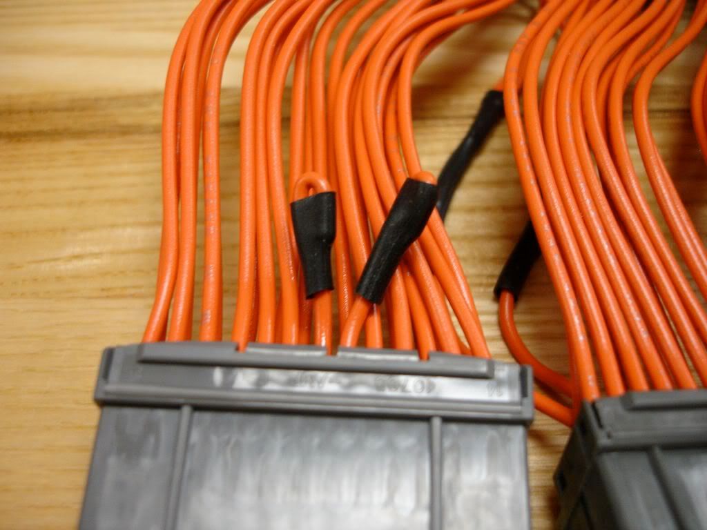
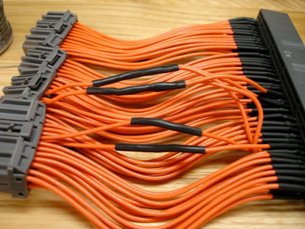
Like I was trying to explain in the previous post, the top picture shows 20 and 21 at the ECU end of the harness are now disconnected. 20 on the vehicle end of the harness is connected to 32, and 21 is connected to 34.
87 has been disconnected altogether.
32 and 34 were swapped with each other since the Evo 6 is different than the Evo 5.
8 and 22 were swapped with each other.
This is an Evo 8 ecu going into an Evo 6 TME.
The fan pulses on/off with the ignition switch turned to "on". I agree it sounds like the PWM lead, which I show as pin 21 on the Evo 8. But as you can tell, pin 21 is not connected to anything from the ECU, so how is the PWM signal pulsing the fan?
- gobbles
- Posts: 18
- Joined: Sat Jun 30, 2007 4:56 pm
![]() by gobbles » Tue Jun 24, 2008 5:57 pm
by gobbles » Tue Jun 24, 2008 5:57 pm
Got the wiring harness sorted (thanks Cossie) and have the rear O2 disabled via the ECU PERIPHERY setting at faa.
Still throwing:
P0135 Heated Oxygen Sensor Heater circuit Bank 1 Sensor 1
My TME only has one O2 sensor (front) and it is the 4 wire type.
Any ideas?
Still throwing:
P0135 Heated Oxygen Sensor Heater circuit Bank 1 Sensor 1
My TME only has one O2 sensor (front) and it is the 4 wire type.
Any ideas?
- gobbles
- Posts: 18
- Joined: Sat Jun 30, 2007 4:56 pm
![]() by Hubbard 0 » Tue Nov 18, 2008 12:49 pm
by Hubbard 0 » Tue Nov 18, 2008 12:49 pm
gobbles wrote:Here are pics of the harness:
[img]http://i252.photobucket.com/albums/hh27/labrat1123/harness/DSC00004.jpg[/ig]
[img]http://i252.photobucket.com/albums/hh27/labrat1123/harness/DSC00005.jpg[/ig]
Like I was trying to explain in the previous post, the top picture shows 20 and 21 at the ECU end of the harness are now disconnected. 20 on the vehicle end of the harness is connected to 32, and 21 is connected to 34.
87 has been disconnected altogether.
32 and 34 were swapped with each other since the Evo 6 is different than the Evo 5.
8 and 22 were swapped with each other.
This is an Evo 8 ecu going into an Evo 6 TME.
The fan pulses on/off with the ignition switch turned to "on". I agree it sounds like the PWM lead, which I show as pin 21 on the Evo 8. But as you can tell, pin 21 is not connected to anything from the ECU, so how is the PWM signal pulsing the fan?
Where did you get your harness? I don't need one built for me, I just need the connectors and metal pins for the connectors.
- Hubbard 0
- Posts: 9
- Joined: Sun Nov 16, 2008 1:01 am
Re: Evo ECU Conversion
![]() by todd-w » Thu Dec 25, 2008 5:01 pm
by todd-w » Thu Dec 25, 2008 5:01 pm
for those of you swapping later ecu into evo4/3/2/1 and still want to retain the stock 2 wire o2 sensor and need to disable the heater circuit cel use 16d0 in ecu periphery ,enter as 0x16d0.
This doesnt affect the o2 signal circuit only the heater circuit.
This doesnt affect the o2 signal circuit only the heater circuit.
- todd-w
- Posts: 330
- Joined: Tue Nov 14, 2006 3:01 pm
- Location: Ireland
59 posts
• Page 4 of 4 • 1, 2, 3, 4
Who is online
Users browsing this forum: No registered users and 25 guests